CNC Stuff:
Below are some of things to consider when using a CNC router/mill. I explained it to Andre like this. You have four major factors: Material, Geometry, Tooling, and Machine Limits. Within each of those is a subset of ~6 factors, each of those with a subset of ~6 factors. Getting really good at it means being aware of 4x6x6 parameters. That's like, over a hundred I think.
In addition, these machines are really designed for industrial operations; thing that happen the same way 10's of 1000's of times. That affords a few mistakes in the beginning.
Here, we try to get everything perfect the very first time. That means the process is often a slow grind of checking, double and triple checking those ~156 parameters. Have fun!
It is best to check your work with someone whose had lots of experiences, until you gain you own.
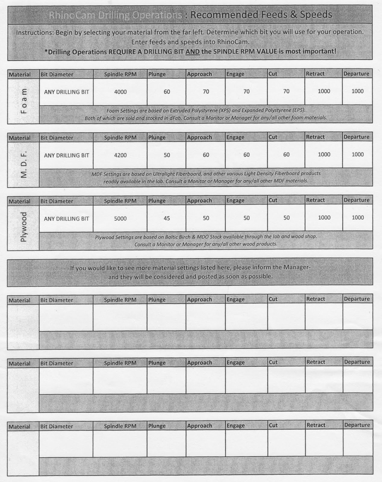
Feeds and Speeds and Cut Depths for RhinoCam
Guess who provided these...
Here you'll find answers to your questions about feed/speed, and also, how to set your "cut depths" based tool diameter and material.
_____________________________________________________
_____________________________________________________
RhinoCAM for CNC machining
RhinoCAM "Drilling" operations
RhinoCAM "Profiling" operations
These setup tutorials were created by Zach Ali for dFab. This is, therefore, the best resource for learning and applying RhinoCAM to your Rhino files.
Additionally, there are online resources to help you move forward. RhinoCAM can be opened from the RhinoCAM menu on machines in the studio hall way, and in dFab. One item in the menu will direct you to video tutorials on how to proceed through various processes/operations.

Questions may be directed to Zack Jacobson-Weaver, OR Zach Ali.
______________________________________________________
______________________________________________________
CNC: Software to Hardware


______________________________________________________
More Useful FREE Rhino Tutorials on Lynda.com
Video Tutorial: Rhino for Solid Modeling (review)
Rhino File Here
3D Topics and Keywords
_____________________________________________________
_____________________________________________________
Organizing Files for Workflow
To concur fully with what Josh presented after lecture on Friday 9/27 I've posted images of a project you saw in that lecture. There are notable similarities. Rhino should not only be the tool for designing an object, but one for designing a comprehensive project execution.
_____________________________________________________
_____________________________________________________
Feeds and Speeds and Cut Depths for RhinoCam
Guess who provided these...
Here you'll find answers to your questions about feed/speed, and also, how to set your "cut depths" based tool diameter and material.
_____________________________________________________
_____________________________________________________
RhinoCAM for CNC machining
RhinoCAM "Drilling" operations
RhinoCAM "Profiling" operations
These setup tutorials were created by Zach Ali for dFab. This is, therefore, the best resource for learning and applying RhinoCAM to your Rhino files.
Additionally, there are online resources to help you move forward. RhinoCAM can be opened from the RhinoCAM menu on machines in the studio hall way, and in dFab. One item in the menu will direct you to video tutorials on how to proceed through various processes/operations.
Questions may be directed to Zack Jacobson-Weaver, OR Zach Ali.
______________________________________________________
______________________________________________________
CNC: Software to Hardware
______________________________________________________
Joining
Joining techniques by family:

Pre-Drilling guides for fasteners

Great website for choosing adhesives:
http://thistothat.com
Remember: These are brand name items. What's most important is the chemical.
Welding
You are MIG welding. M= Metal! I = Inert G = Gas. You have a filler metal, shielded in inert gas, all being applied simultaneously at the pull of a trigger.
There is a ratio between those parameters and the thickness of the metal you're working with we call, generically, feed & speed (remember this). It's predictable, until YOU get in the system. Use the chart below to get started.
Miller Settings Calculator
The rest, as with finishing, is practice.
Mold-Making/ Casting:
Below are some of things to consider when using a CNC router/mill. I explained it to Andre like this. You have four major factors: Material, Geometry, Tooling, and Machine Limits. Within each of those is a subset of ~6 factors, each of those with a subset of ~6 factors. Getting really good at it means being aware of 4x6x6 parameters. That's like, over a hundred I think.
In addition, these machines are really designed for industrial operations; thing that happen the same way 10's of 1000's of times. That affords a few mistakes in the beginning.
Here, we try to get everything perfect the very first time. That means the process is often a slow grind of checking, double and triple checking those ~156 parameters. Have fun!
It is best to check your work with someone whose had lots of experiences, until you gain you own.
Feeds and Speeds and Cut Depths for RhinoCam
Guess who provided these...
Here you'll find answers to your questions about feed/speed, and also, how to set your "cut depths" based tool diameter and material.
 |
| Drilling |
 |
| 2-1/2 Axis Operations include Profiling and...Pocketing |
_____________________________________________________
_____________________________________________________
Cut Direction in CNC milling
The direction in which the tool moves in CNC milling can effect the quality of a cut. Especially with wood and wood products, the way in which the tool engages the material is as important as the feed (how fast the tool moves into the material) and speed (how quickly the tool spins). What is the best way to find the most effective cut direction for your material? "Climb" or "Conventional"?
 |
| Image by George Stanton |
_____________________________________________________
RhinoCAM for CNC machining
RhinoCAM "Drilling" operations
RhinoCAM "Profiling" operations
These setup tutorials were created by Zach Ali for dFab. This is, therefore, the best resource for learning and applying RhinoCAM to your Rhino files.
Additionally, there are online resources to help you move forward. RhinoCAM can be opened from the RhinoCAM menu on machines in the studio hall way, and in dFab. One item in the menu will direct you to video tutorials on how to proceed through various processes/operations.
Questions may be directed to Zack Jacobson-Weaver, OR Zach Ali.
______________________________________________________
______________________________________________________
CNC: Software to Hardware
These are the last steps of moving from RhinoCam files to running the 3-axis CNC router. Some are software details, some are hardware details. You will review this and be given a demo on 10/30. This is in preparation for your next assignment to be posted soon…
Additional resources can be found at the dFab website, under tutorials, which Zach is updating almost daily.
- Machine Definition: The PCs in the studio do not list the actual machine you'll be using. It is necessary to set this properly. In dFab, your files should default to "RC_CNTMOTION950_3AXIS_ROUTER". If you don't see this, you can change it in the "Program" tab under "Post".

- Lead In/ Lead Out: Routing tools are not like drill bits. They are not made to cut straight down. Will they? Yes. Is it good for them? No. They get too hot (fire!), and they get dull at the tip. They are very expensive so we have to treat them properly. One way to do this is to use Entry/Exit options in RhinoCAM to make sure the tools are never cutting straight down. When you're plunging down into material, you can also be moving sideways. This is effectively like a ramp that lowers the tools to a target depth. In 2-1/2 axis operations you can set this under the Entry/Exit tab.
There you can choose the option, "Along Path 3D Entry". When you click this option your are given two parameters, "Along Path Angle" and "Along Path Height". Guess what they do! Use these options and notice how your tool path changes. You should now be 'ramping' into the material, never cutting straight down. Good for tools = Good for you.


- Tool Numbers: CNC tools in dFab can be preloaded from a library created by Zach Ali. You can also create tools from the Tool tab of each operations folder. In that folder, there is a parameter for "Tool #" (not "# of Flutes" (cutting edges)) This needs to correspond exactly with the position of the tools on the machine.
Tools are numbered 1-9 from left to right (as seen from the controller computer) If/when you change or use your own tools, you need to accurately record its position and enter that into RhinoCAM.

- - - - - - - - - - - - - - - - - - - - - - - - - - - - - - - - - - - - - - - - - - - - - - - - - - - - - - - - - - - - - - - - - - - - - - -
- Posting NC Files to the CNC Server: Who does RhinoCAM work for!? When you've verified all of your settings, it's time to POST. You can right-click on the OPERATIONS folders to post processes individually, or click on the top "Setup 1" folder to post all processes in the order in which they appear. Select POST and...

- A file directory window will pop up. Your file goes in dFAB DropBox - CNC Router > Undergraduate Students > 2nd Year > (create a file with your andrew id). The default file type (.nc) is what you want. And then...

- A text editor will pop up. From here you can verify lots of stuff. Check that tool numbers are correct. And then...

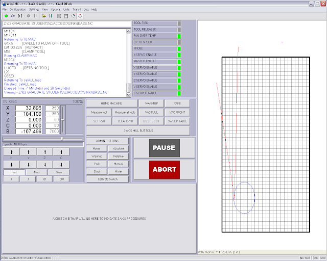
- Search for NEGATIVE Z values. If you sift through the G-code, you notice x,y,z coordinates (along with a ton of other code). Those coordinates position the bottom tip of the cutting tool. Because our material setup places z0 at the top of the CNC bed, we know we don't want the tool to move below that. We can, therefore, do a search of the G-code for "z-" values. Hit Control-F to use the finder. Enter z- and hit the "next" button. In the image below, you see the very bottom line of code has a z- value. This is okay. There are other places you may see z- values such as directly following a tool change. In the code you may spot "Tn" several lines above these z- values, where n should be a tool number you've deliberately selected. If you have questions about z- values in your code, check with a monitor or Zach A. Improper z- values will stop the machine in the middle of your cut.

- - - - - - - - - - - - - - - - - - - - - - - - - - - - - - - - - - - - - - - - - - - - - - - - - - - - - - - - - - - - - - - - - - - - - - -
- - - - - - - - - - - - - - - - - - - - - - - - - - - - - - - - - - - - - - - - - - - - - - - - - - - - - - - - - - - - - - - - - - - - - - -
Fixtures: Fixtures are like dentures. They grab onto existing structures and arrange external objects in particular relationship to that structure.
The table is equipped with a vacuum to hold flat materials down. This is basically a fixture.
As you gain experience with the router, you will find new ways to fix materials in place. For now, please consult with a monitor, Zach A, or your instructors when designing a fixture.
- - - - - - - - - - - - - - - - - - - - - - - - - - - - - - - - - - - - - - - - - - - - - - - - - - - - - - - - - - - - - - - - - - - - - - -
- - - - - - - - - - - - - - - - - - - - - - - - - - - - - - - - - - - - - - - - - - - - - - - - - - - - - - - - - - - - - - - - - - - - - - -
- WinCNC: The last soft step. WinCNC is like the Epilog Driver for the laser cutter. It's the last step before hitting the 'Go' button.
WinCNC can interface with the machine in many ways. Some useful ways are listed here:
- Command Line: Like Rhino, you'll see important prompts here. You can also enter commands. Type "T2" and "Enter". The machine will pick up the tool in the #2 holder.
- Preview: When you File > Open your .nc file, you can preview the geometry with this button.
- The "Jog" controls move the spindle around the table. This can be done at different speeds and intervals on each axis. X and Y can also be moved with the arrow keys on the keyboard.
- There is a slider that can change the speed the machine is running. Make sure this starts at 100%. You'll learn when to change this with experience.
- Measure Tool....well, it measures the tool. If you have typed "T2" and the machine has picked it up, you can press Measure Tool and see how the machine does this.
- The dust boot covers the tool and helps the dust collector sweep up dust as the machine cuts. It can get in the way. You'll learn when to raise/lower it with experience.
- Pause: First course of action if there's a problem. This will leave the spindle running! If you pause to clear an obstruction do not get close to the spindle! You are softer than plywood. Pause is also engaged with the spacebar on the keyboard.
- Abort: Major problem. Stop everything. This includes shifting or lifted materials. Broken tools. Incorrect tool paths. Etc. Etc. Etc. Etc. Etc. ***Another way to engage the abort is by pulling the bright pink cord surrounding the table. This requires a reboot of the whole machine, but it can be the fastest way to respond to a bad situation.

Open your file from the dFab CNC Dropbox. The name of your file will appear in the Command line window.

When you see your file in the Command Line, click the preview button (2). This will show you what the geometry of the tool path looks like.

Press "Enter" once, you'll see a list of your tools to finally verify. Pressing "Enter" again = "GO!". Be prepared to pause or abort if anything seems amiss. And also...

Turn on the dust collector. This will help reduce the amount of clean up necessary when your cut is complete. Finally...

dFab cannot afford another mop cat. Cleaning up a shop is not a chore. It is our privilege to have this space. It is an honor to work in the environment Zach has created. WE will keep it clean. If we find it dirty, we will show others how it's done. If you want this space, you should earn it.
More Useful FREE Rhino Tutorials on Lynda.com
Video Tutorial: Rhino for Solid Modeling (review)
Rhino File Here
3D Topics and Keywords
- Solids menu: extrude planar curve, pipe, tube, cap planar holes (primitives: box, sphere, etc...)
- Surface menu: revolve, sweep 1 rail, extrude curve, loft
- Boolean operations: Union, Difference, Split
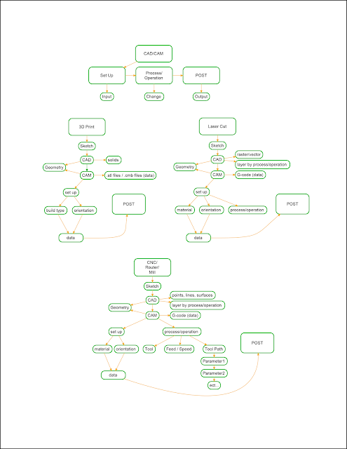
CAD/CAM Overview

_____________________________________________________
_____________________________________________________
Organizing Files for Workflow
To concur fully with what Josh presented after lecture on Friday 9/27 I've posted images of a project you saw in that lecture. There are notable similarities. Rhino should not only be the tool for designing an object, but one for designing a comprehensive project execution.
 |
| The object and its constituent parts, to scale, with notation. |
 |
| The parts organized as individual pieces with machining processes delineated by color, geometry and layer. |
 |
| The parts, including fixtures and jigs for machining organized into cut sheets. |
 |
| First assembly. |
 |
| Finished project. |
_____________________________________________________
Feeds and Speeds and Cut Depths for RhinoCam
Guess who provided these...
Here you'll find answers to your questions about feed/speed, and also, how to set your "cut depths" based tool diameter and material.
|
| Drilling |
|
| 2-1/2 Axis Operations include Profiling and...Pocketing |
_____________________________________________________
_____________________________________________________
Cut Direction in CNC milling
The direction in which the tool moves in CNC milling can effect the quality of a cut. Especially with wood and wood products, the way in which the tool engages the material is as important as the feed (how fast the tool moves into the material) and speed (how quickly the tool spins). What is the best way to find the most effective cut direction for your material? "Climb" or "Conventional"?
|
| Image by George Stanton |
_____________________________________________________
RhinoCAM for CNC machining
RhinoCAM "Drilling" operations
RhinoCAM "Profiling" operations
These setup tutorials were created by Zach Ali for dFab. This is, therefore, the best resource for learning and applying RhinoCAM to your Rhino files.
Additionally, there are online resources to help you move forward. RhinoCAM can be opened from the RhinoCAM menu on machines in the studio hall way, and in dFab. One item in the menu will direct you to video tutorials on how to proceed through various processes/operations.
Questions may be directed to Zack Jacobson-Weaver, OR Zach Ali.
______________________________________________________
______________________________________________________
CNC: Software to Hardware
These are the last steps of moving from RhinoCam files to running the 3-axis CNC router. Some are software details, some are hardware details. You will review this and be given a demo on 10/30. This is in preparation for your next assignment to be posted soon…
Additional resources can be found at the dFab website, under tutorials, which Zach is updating almost daily.
- Machine Definition: The PCs in the studio do not list the actual machine you'll be using. It is necessary to set this properly. In dFab, your files should default to "RC_CNTMOTION950_3AXIS_ROUTER". If you don't see this, you can change it in the "Program" tab under "Post".
- Lead In/ Lead Out: Routing tools are not like drill bits. They are not made to cut straight down. Will they? Yes. Is it good for them? No. They get too hot (fire!), and they get dull at the tip. They are very expensive so we have to treat them properly. One way to do this is to use Entry/Exit options in RhinoCAM to make sure the tools are never cutting straight down. When you're plunging down into material, you can also be moving sideways. This is effectively like a ramp that lowers the tools to a target depth. In 2-1/2 axis operations you can set this under the Entry/Exit tab.
There you can choose the option, "Along Path 3D Entry". When you click this option your are given two parameters, "Along Path Angle" and "Along Path Height". Guess what they do! Use these options and notice how your tool path changes. You should now be 'ramping' into the material, never cutting straight down. Good for tools = Good for you.
- Tool Numbers: CNC tools in dFab can be preloaded from a library created by Zach Ali. You can also create tools from the Tool tab of each operations folder. In that folder, there is a parameter for "Tool #" (not "# of Flutes" (cutting edges)) This needs to correspond exactly with the position of the tools on the machine.
Tools are numbered 1-9 from left to right (as seen from the controller computer) If/when you change or use your own tools, you need to accurately record its position and enter that into RhinoCAM.
- - - - - - - - - - - - - - - - - - - - - - - - - - - - - - - - - - - - - - - - - - - - - - - - - - - - - - - - - - - - - - - - - - - - - - -
- Posting NC Files to the CNC Server: Who does RhinoCAM work for!? When you've verified all of your settings, it's time to POST. You can right-click on the OPERATIONS folders to post processes individually, or click on the top "Setup 1" folder to post all processes in the order in which they appear. Select POST and...
- A file directory window will pop up. Your file goes in dFAB DropBox - CNC Router > Undergraduate Students > 2nd Year > (create a file with your andrew id). The default file type (.nc) is what you want. And then...
- A text editor will pop up. From here you can verify lots of stuff. Check that tool numbers are correct. And then...
- Search for NEGATIVE Z values. If you sift through the G-code, you notice x,y,z coordinates (along with a ton of other code). Those coordinates position the bottom tip of the cutting tool. Because our material setup places z0 at the top of the CNC bed, we know we don't want the tool to move below that. We can, therefore, do a search of the G-code for "z-" values. Hit Control-F to use the finder. Enter z- and hit the "next" button. In the image below, you see the very bottom line of code has a z- value. This is okay. There are other places you may see z- values such as directly following a tool change. In the code you may spot "Tn" several lines above these z- values, where n should be a tool number you've deliberately selected. If you have questions about z- values in your code, check with a monitor or Zach A. Improper z- values will stop the machine in the middle of your cut.
- - - - - - - - - - - - - - - - - - - - - - - - - - - - - - - - - - - - - - - - - - - - - - - - - - - - - - - - - - - - - - - - - - - - - - -
- - - - - - - - - - - - - - - - - - - - - - - - - - - - - - - - - - - - - - - - - - - - - - - - - - - - - - - - - - - - - - - - - - - - - - -
Fixtures: Fixtures are like dentures. They grab onto existing structures and arrange external objects in particular relationship to that structure.
The table is equipped with a vacuum to hold flat materials down. This is basically a fixture.
As you gain experience with the router, you will find new ways to fix materials in place. For now, please consult with a monitor, Zach A, or your instructors when designing a fixture.
- - - - - - - - - - - - - - - - - - - - - - - - - - - - - - - - - - - - - - - - - - - - - - - - - - - - - - - - - - - - - - - - - - - - - - -
- - - - - - - - - - - - - - - - - - - - - - - - - - - - - - - - - - - - - - - - - - - - - - - - - - - - - - - - - - - - - - - - - - - - - - -
- WinCNC: The last soft step. WinCNC is like the Epilog Driver for the laser cutter. It's the last step before hitting the 'Go' button.
WinCNC can interface with the machine in many ways. Some useful ways are listed here:
- Command Line: Like Rhino, you'll see important prompts here. You can also enter commands. Type "T2" and "Enter". The machine will pick up the tool in the #2 holder.
- Preview: When you File > Open your .nc file, you can preview the geometry with this button.
- The "Jog" controls move the spindle around the table. This can be done at different speeds and intervals on each axis. X and Y can also be moved with the arrow keys on the keyboard.
- There is a slider that can change the speed the machine is running. Make sure this starts at 100%. You'll learn when to change this with experience.
- Measure Tool....well, it measures the tool. If you have typed "T2" and the machine has picked it up, you can press Measure Tool and see how the machine does this.
- The dust boot covers the tool and helps the dust collector sweep up dust as the machine cuts. It can get in the way. You'll learn when to raise/lower it with experience.
- Pause: First course of action if there's a problem. This will leave the spindle running! If you pause to clear an obstruction do not get close to the spindle! You are softer than plywood. Pause is also engaged with the spacebar on the keyboard.
- Abort: Major problem. Stop everything. This includes shifting or lifted materials. Broken tools. Incorrect tool paths. Etc. Etc. Etc. Etc. Etc. ***Another way to engage the abort is by pulling the bright pink cord surrounding the table. This requires a reboot of the whole machine, but it can be the fastest way to respond to a bad situation.
Open your file from the dFab CNC Dropbox. The name of your file will appear in the Command line window.
When you see your file in the Command Line, click the preview button (2). This will show you what the geometry of the tool path looks like.
Press "Enter" once, you'll see a list of your tools to finally verify. Pressing "Enter" again = "GO!". Be prepared to pause or abort if anything seems amiss. And also...
Turn on the dust collector. This will help reduce the amount of clean up necessary when your cut is complete. Finally...
dFab cannot afford another mop cat. Cleaning up a shop is not a chore. It is our privilege to have this space. It is an honor to work in the environment Zach has created. WE will keep it clean. If we find it dirty, we will show others how it's done. If you want this space, you should earn it.
______________________________________________________
Joining
Joining techniques by family:
Pre-Drilling guides for fasteners
Great website for choosing adhesives:
http://thistothat.com
Remember: These are brand name items. What's most important is the chemical.
Welding
You are MIG welding. M= Metal! I = Inert G = Gas. You have a filler metal, shielded in inert gas, all being applied simultaneously at the pull of a trigger.
There is a ratio between those parameters and the thickness of the metal you're working with we call, generically, feed & speed (remember this). It's predictable, until YOU get in the system. Use the chart below to get started.
Miller Settings Calculator
The rest, as with finishing, is practice.
Mold-Making/ Casting:

Mold making can be done with rigid or soft materials and really only has three principals, all of which are inextricably related:
- Release agents: Prevent bonding
- Parting lines: Subdivide molds into removable pieces
- Draft angles: Allow pieces to be assembled/ dissembled in order

Flexible polyurethane mold with rigid "mother mold".

Molds can exploit material properties through their own geometry.

Molds can be the best (or only) way to achieve certain material characteristics.


Molding and casting materials are interchangeable. Some molds are one time use (waste molds), and others are for multiples (production molds).
Sources:
No comments:
Post a Comment